We present an environment for multimodal visualization of geometrical constructions, including both graphical and textual realizations. The graphic interface is programmed by direct manipulation, and this process is mirrored in the text. The text resembles a program written in a classical programming language, but no computer science knowledge is required. The guiding principle is that of textual and graphical equivalence: the same linguistic resources are used for graphical construction and for text generation. During construction, the names of several tools appear in pop-up menus. As the tools are used, their names are written in the text, and geometrical objects are simultaneously drawn in the figure and written in the text. Text can be produced in a variety of ³ dialects² according to the user's mother tongue. Moreover, the visualization system can be used for interfaces which include a facility for programming by demonstration (with macro definitions) and can offer textual support for interaction through other media.
Plan
In this paper, we present an environment for multimodal (graphical and textual) visualization of geometrical constructions. We first present CabriII, the program on which this work is based. In the second section, we elaborate on the definition of macro-constructions using this software. Some of the reasons for introducing such a textual view in a geometry program are explained in section three. The next section focuses on the choices that have guided development. The last section discusses results and perspectives.
CabriII (or Cabri-géomètre II) is a direct manipulation program for interactive ³exploration² of geometrical diagrams [Laborde 85]. Many mathematics teachers and mathematicians use it for teaching or for their own work. It is the result of a tight collaboration between mathematicians, software researchers, educators, and teachers in everyday contact with pupils.
Using this software, the user is immersed in an intelligent microworld. CabriII is an excellent learning environment for geometry [Laborde 89], [Laborde 95]. Users construct geometrical diagrams and create new tools with macro-constructions. A teacher can profile the environment for specific learning tasks by embedding macro-constructions in his or her own tools. Through interactive manipulation of geometrical constructions, a pupil may for instance observe invariant properties and recognize them as constraints. All objects (for example, geometric objects and interface elements) are manipulated directly.

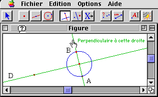
Figure 1 shows a geometrical diagram drawing in CabriII. The diagram represents a point A, a line D and some other geometrical objects used to construct the symmetrical point (called B) of point A with respect to the line.
CabriII can store as ³macros² construction methods which users try out. This term is commonly used in the domain of programming by demonstration.
The aim of writing a macro is to define a new tool by using a list of repeatedly invoked constructions [Sugiura 96]. For instance, it is possible to define a macro to construct the symmetric point of a given point with respect to a line.
As a matter of fact, CabriII does not store the whole construction, but only its ³useful² part, determined automatically when the user indicates the ³initial² and ³final² objects of the construction. This method lets the user decide to construct a macro after embarking on a complex construction, rather than before. It also minimizes the length of the macro (which is strongly related to the number of objects retained). A consequence of this freedom is that a macro definition has to pass a validation test which can fail for various reasons, such as omission of necessary initial objects, dependency loops (in which an initial object depends on a final object), etc.
Figure 2 shows the dependencies between geometrical objects in the definition of a construction method for drawing the symmetric point of a given point. The method chosen is the same as in figure \ref{fig-mSym-const}. The object names are written in order of their creation, from left to right. The names written in single quotes are the names displayed in the diagram, and arrows are used to represent object dependencies. The selected initial object names are surrounded by thin rectangles, and the selected final objects by thicker ones. The macro creation process extracts the smallest graph that connects the final objects to the initial ones.

Notice that the macro obtained may not correspond exactly to the user's expectations if s/he has made mistakes in certain construction choices. In that case, the user must debug the macro. Using the text form is far better for that purpose than redoing the whole construction.
Why is a textual view used in geometry?
In mathematics, graphical visualization is a fundamental support for reasoning [Zimmermann 91]. The appearance of dynamic geometry opens new doors by making the concept of diagraming more accessible: simply drawing, by contrast, is more static and discrete.
However, in purely graphical interfaces, the choices which guide the construction of various diagram objects can only be tracked down by observing their effect, i.e. by observing the relative behavior of the objects throughout diagram deformations. There is no longer direct access to the causes, only to the consequences. The information displayed is not a complete history including the creation, deformations and deletion of all objects, but rather only a record of the construction steps (dependencies) of the stored objects. One way to display all of the constraints for the whole diagram would be to display the program which drew the diagram.
Similarly, we can observe that macro definition is closely related to classical programming, so that a textual medium becomes an absolute must. We can also add to the software the full range of classical programming environment tools, such as a step-by-step replay tool associated with cursor progression, or a tool aiding visualization of the correspondence between object value and graphic rendering. Specific tools associated with the relevant domain (dynamic geometry) are also useful. For instance, the use of color allows visualization of dependencies between objects, and aids debugging if the macro validation fails.
Constraints, choices, and shape
Given the target audience for this software, the programming langage chosen is as close as possible to the graphic interface. The display is based on the concept of textual and visual equivalence [Lecolinet 96] - although in this case ³graphical² might be a better term than ³visual².
Text generation, object ubiquity
Ubiquity is the ability to be in several places at the same time. In the case of a multimodal interface in a geometry program, ubiquity can be applied to geometrical objects such as points, straight lines, circles, conics, and so on as shown below: to construct a new geometrical object, the user selects a tool, then goes to the diagram and specifies the objects to which that tool is to be applied. Only objects whose types are appropriate for the current tool can be selected. CabriII produces demonstration strings which help the user to choose which objects to select and to understand how they will be used by the current tool. Alongside the construction, tools names are displayed in the textual area, and strings are simultaneously displayed in the textual area and under the cursor in the graphical area, along with the names which identify objects.
Moves in construction sequences
The user can revise a diagram construction by clicking on recorder buttons. The geometrical objects appear in their drawing order with respect to the object dependency constraints (or disappear according to the selected recorder buttons). The corresponding text for that move in the sequence of effective objects is produced in two colors: flat black for the drawn objects and light blue for the object to be drawn. A third color (red) is used to display current program elements: when the user moves through the macro's internal objects, the programming langage commands are displayed in red.
Value modification
A ³program² is a formal description of the active constructions. Actual values of objects and graphical attributes (color, thickness, and so on) may be displayed in help bubbles associated with the object names. Clicking on a name causes every textual occurrence of the relevant object to be highlighted in green. With a double click, all textual occurrences of the objects which depend on the selected object are also displayed in green, and a help bubble appears.
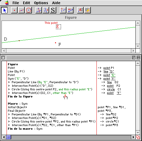
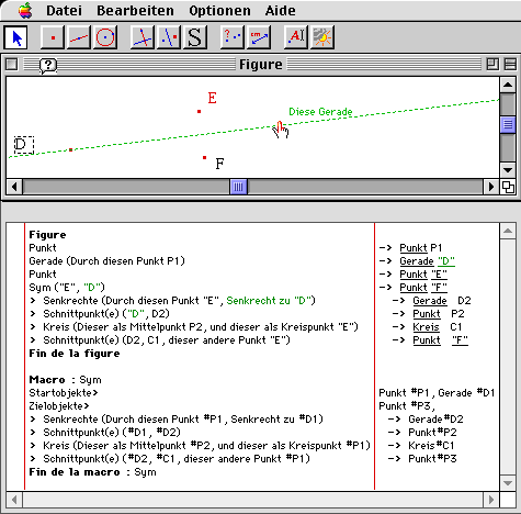
Figures 3 and 4 show a diagram and its textual view respectively in English (i.e. when the language chosen by the user is English) and in German. In this diagram, the macro ³Sym² is called on point E with respect to line D and constructs point F.


The best way to edit macro constructions is not yet clear. We are investigating whether editing would be most helpful in the diagram program or directly in the macro program.
The equivalence of the material presented textually and visually enables every user to program comfortably. The user does not have to type a single character, yet appropriate text is generated in the current dialog language of the interface. The text verifies relevant lexical and syntactic rules. Since the syntax and semantics of the programming language are made obvious, the user learns them easily.
We have presented an environment for the display of geometrical data which emphasizes coordinated textual and graphical presentation of equivalent material and the ubiquity of micro-world objects. The textual view is an important aid to the construction of macros. The environment can facilitate exploration of macro debugging techniques and has relevance for studies of translation from readable diagram programs to natural language instructions. It is also designed for use in support of other interactive media.
Copyright
Copyright to the above work is hereby
transferred to the Association for Computational Linguistics
(ACL)
Date de la dernière mise à jour : mercredi 1 juillet 1998